Ducted ventilation systems often look straightforward on a drawing, but the actual layout can involve a surprising number of practical decisions once work starts on site. Air needs to travel through connected sections while equipment, walls, ceilings, machinery, and service areas all compete for the same limited space.
A fan, because of this, isn't really an isolated component sitting off on its own. Its shape, installation position, connection with the duct, and relationship with surrounding equipment can shape how the entire airflow route gets arranged.
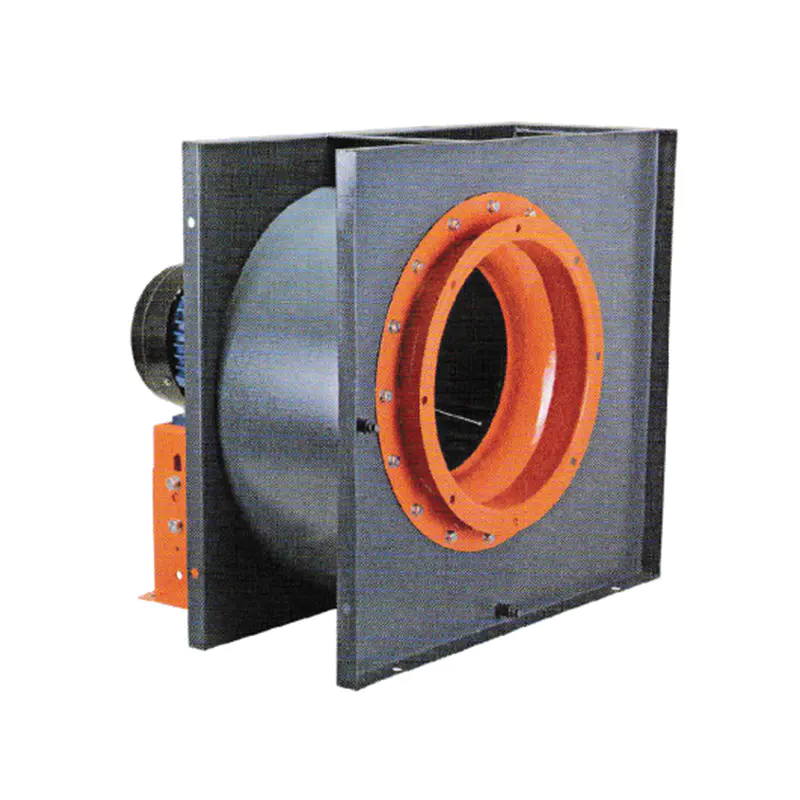
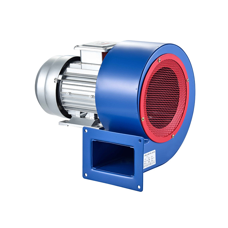
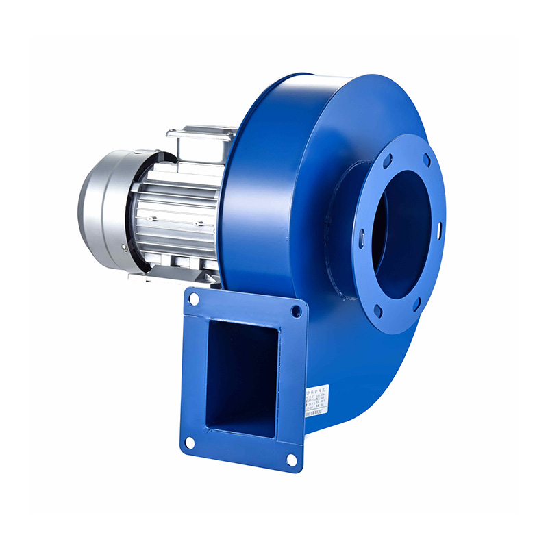
A Square Inline Centrifugal Fan offers a compact approach for systems where available installation space needs careful planning from the start. Its inline arrangement lets the fan sit within a ducted path rather than demanding a large separate equipment area off to the side.
That can give designers more room to breathe when planning air supply and exhaust routes through a building. The idea matters especially for industrial HVAC systems, workshops, commercial buildings, equipment rooms, and other spaces where ventilation has to work around structures that were already there first.
Why Does Fan Shape Matter in Ducted Airflow Layouts?
Duct systems rarely enjoy unlimited space to work with. A ventilation route may pass above a ceiling, along a wall, through a service area, or around other building equipment already claiming that same footprint.
A fan that fits naturally into the duct path makes these arrangements a lot easier to organize on paper and in practice. The shape of the fan becomes part of the layout decision itself, not an afterthought bolted on later.
| Layout Concern |
Possible Fan Design Consideration |
| Narrow service area |
Compact installation arrangement |
| Long duct route |
Suitable inline positioning |
| Limited ceiling space |
Practical equipment placement |
| Multiple duct sections |
Convenient connection points |
| Equipment-dense area |
Reduced interference with surrounding systems |
A Square Inline Centrifugal Fan can sit directly within a ducted airflow route rather than needing its own room. This arrangement can cut down on the need to carve out a separate area just for the fan housing.
The square form can also fit naturally alongside rectangular duct systems already common in commercial buildings. That doesn't mean every ventilation project should reach for the same fan configuration by default. The right choice depends on the duct layout, airflow direction, installation environment, and service requirements at hand. The important point is that physical design can genuinely expand how much freedom a designer has when arranging the system.
How Can an Inline Arrangement Help Improve Air Supply Paths?
Air supply paths need to connect the fan with the areas that actually require ventilation, not just the nearest convenient spot. A poorly planned route can create unnecessary bends, crowded service spaces, or maintenance access that's a headache to reach later.
An inline fan can provide a direct connection between different duct sections without much detour. That tends to make the overall arrangement easier to picture during the design stage before anything gets built.
| Airflow Layout |
Inline Fan Application |
| Straight duct section |
Fan positioned within the route |
| Branching system |
Fan placed according to system layout |
| Ceiling ventilation |
Equipment integrated into overhead ducting |
| Industrial exhaust |
Installed along the planned exhaust route |
| Room-to-room air movement |
Supports connected duct paths |
The fan doesn't dictate the entire duct design on its own, of course. Duct length, bends, outlets, filters, dampers, and room conditions all shape the final arrangement together.
Still, an inline configuration gives the designer another option when space runs tight. The fan can become part of the route itself instead of occupying a separate spot beside it, taking up room that isn't really there. That's particularly useful in renovation projects where existing building structures leave little room to squeeze in new equipment.
Can Square Inline Centrifugal Fan Help With Space Utilization?
Space utilization is a real, practical concern in industrial HVAC design, not just a checkbox on a spec sheet. Mechanical rooms often already hold pumps, electrical equipment, pipes, ducts, and other service components jammed together.
Adding ventilation equipment on top of that can create conflicts if the fan needs a large independent installation area of its own. A Square Inline Centrifugal Fan can help designers think about vertical and horizontal space together rather than separately.
Its placement within the duct route may let the available area get used more efficiently overall.
| Installation Area |
Potential Layout Benefit |
| Ceiling void |
Can fit into planned duct routes |
| Service corridor |
Supports inline installation |
| Equipment room |
Can work within connected duct sections |
| Workshop |
Helps organize overhead ventilation |
| Utility area |
May reduce separate fan space |
Space efficiency doesn't simply mean shrinking the equipment down as small as possible. The entire system still needs enough room for installation, inspection, cleaning, and eventual replacement down the road.
A compact arrangement nobody can actually reach later creates its own practical headaches. Because of this, designers need to balance space utilization against service access rather than chasing one at the expense of the other. The fan should fit the duct layout without turning routine maintenance into a struggle.
How Does Equipment Installation Affect Ducted Airflow?
Installation quality shapes how smoothly a ventilation system actually operates once it's running. A fan needs to sit positioned according to the intended airflow direction and connected properly with the surrounding duct sections around it.
The support structure also needs to suit the installation environment it's placed in, not just hold the fan up loosely.
| Installation Consideration |
Practical Purpose |
| Fan orientation |
Matches the intended airflow route |
| Duct connection |
Creates a suitable connection between sections |
| Support structure |
Keeps equipment properly positioned |
| Service access |
Allows routine inspection |
| Surrounding clearance |
Reduces installation interference |
Installation planning should start well before the fan even arrives on site. Designers and contractors can work out where the equipment will actually sit and how workers will physically reach it later.
That matters especially when the fan ends up installed above a ceiling or tucked inside a restricted service area. A well-planned installation makes future inspection noticeably easier. It can also cut down on the need to dismantle unrelated equipment just to service the ventilation system. The practical goal isn't simply squeezing the fan into whatever space happens to be available. It's placing it where airflow, access, and surrounding equipment can genuinely coexist without stepping on each other.
What Is the Difference Between Axial and Centrifugal Fan Layouts?
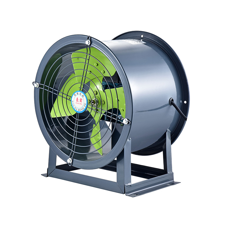
Different fan configurations open up different possibilities for ventilation planning. A China Axial Flow Fan is generally associated with air movement running along the direction of the fan shaft itself.
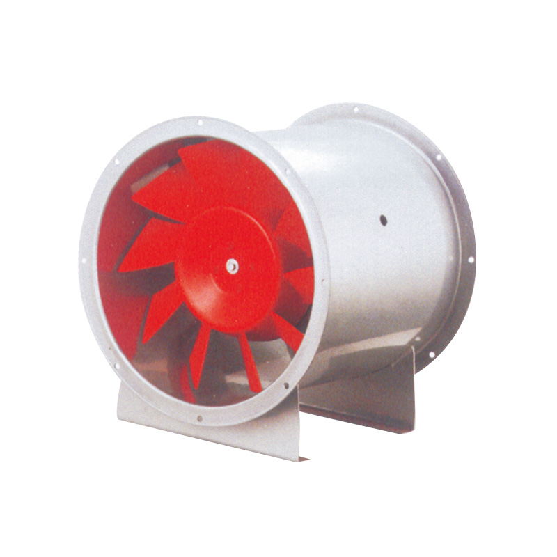
This kind of arrangement tends to suit ventilation systems where the airflow path stays relatively direct without many turns. A Bifurcated Axial Flow Fan uses a different structural arrangement that can suit certain industrial ventilation environments better than a standard axial design.
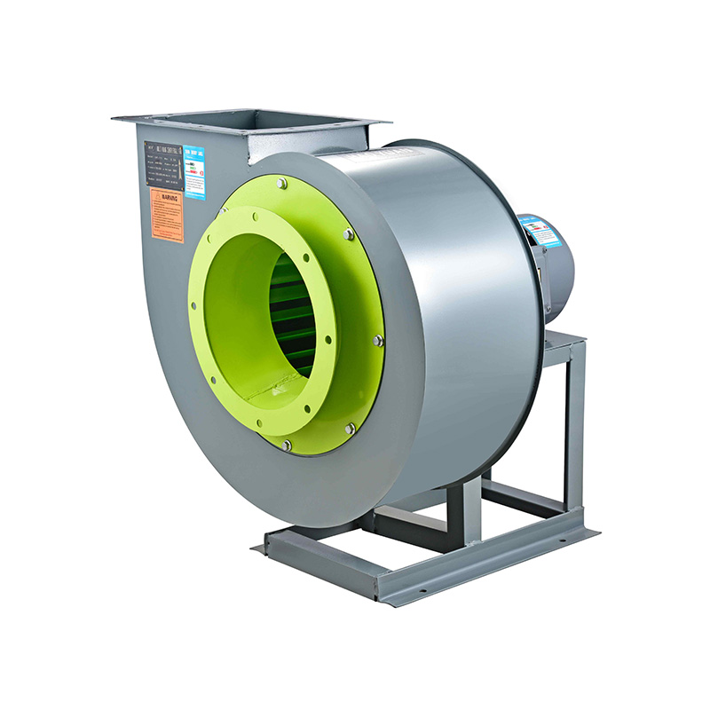
A Centrifugal Air Fan, by comparison, changes the direction of air movement within its housing before that air ever enters the connected duct system.
| Fan Type |
Layout Characteristic |
| China Axial Flow Fan |
Air moves along the fan axis |
| Bifurcated Axial Flow Fan |
Axial arrangement with a separated motor area |
| Square Inline Centrifugal Fan |
Centrifugal fan arranged within a duct path |
| Centrifugal Air Fan |
Suitable for ducted air movement applications |
The choice should rest on the complete ventilation requirement rather than one detail in isolation. A fan that suits an open ventilation area may not be the right pick for a complicated, winding duct route.
Likewise, a compact inline arrangement can prove useful exactly where a larger standalone fan installation would be genuinely difficult to fit. Understanding the physical layout of each fan type helps designers picture how the equipment will actually sit within the wider system, not just how it performs on a spec sheet.
How Can a Centrifugal Air Fan Support Industrial HVAC Systems?
Industrial HVAC systems often carry more complicated airflow routes than a simple single-room ventilation setup. Air may need to move through production areas, storage spaces, workshops, processing rooms, or equipment zones scattered across a facility.
The ventilation system may also need to tie into exhaust routes or air treatment equipment elsewhere in the building. A Centrifugal Air Fan can get incorporated into ducted systems where controlled air movement genuinely matters to the process.
Its use can support layouts where air needs to travel through several connected duct sections in sequence.
| Industrial Area |
Potential Ventilation Role |
| Workshop |
Supports planned air movement |
| Equipment room |
Connects ventilation with duct routes |
| Production area |
Supports air supply or exhaust |
| Storage space |
Works within organized ventilation paths |
| Service area |
Fits into planned duct arrangements |
The fan should get selected according to the actual requirements of the system it's joining, not a generic assumption. Air volume, duct arrangement, environmental conditions, maintenance access, and installation space all deserve consideration together.
A fan shouldn't get picked just because its physical shape looks convenient on paper. The complete airflow route determines whether that shape genuinely suits the job. That's why equipment selection and duct design stay so closely connected in practice.
How Should Designers Plan Fan Position Along the Duct?
Fan placement can shape the organization of the entire ventilation route, not just the immediate area around the fan itself. A fan positioned in an accessible service area tends to be easier to inspect than one buried behind fixed structures.
At the same time, the location still needs to make sense for the direction and purpose of the airflow moving through it. A useful planning process can work through a handful of practical questions.
Where Does the Air Need to Enter or Leave?
Identify the rooms or equipment areas connected to the ventilation system in question.
Where Can the Duct Route Pass Safely?
Review ceilings, walls, machinery, structural elements, and other existing services already in place.
Where Can the Fan Be Accessed?
Leave suitable space for inspection and routine service down the road.
How Will the Duct Connect to the Fan?
Consider the direction and arrangement of the connected sections carefully.
Will Future Maintenance Disturb Other Equipment?
Avoid locations that turn basic service into an unnecessary ordeal.
This approach can head off a common planning mistake before it happens. A fan may fit physically into a location while still being genuinely inconvenient to operate or maintain once it's in.
Good layout planning considers what happens after installation, not only how the system looks on a drawing before anyone's touched a duct.
What Should Be Considered When Choosing a Square Inline Centrifugal Fan?
Selecting a Square Inline Centrifugal Fan involves more than checking whether the equipment physically fits inside the available area. The fan should correspond with the duct structure and the intended ventilation task it's meant to serve.
The surrounding environment matters here too, not just the fan's own dimensions.
| Selection Area |
Question to Consider |
| Duct layout |
Does the fan suit the planned airflow path? |
| Installation space |
Can it be positioned without interfering with other equipment? |
| Service access |
Can workers reach the fan for inspection? |
| Airflow purpose |
Is it intended for supply, exhaust, or another application? |
| Environment |
Does the construction suit the installation location? |
| System connection |
Can the surrounding duct sections be arranged naturally? |
Buyers should also communicate the actual application clearly to the supplier rather than leaving it vague. A supplier needs to understand whether the fan will serve an industrial exhaust route, an HVAC system, a workshop, or some other ventilation application entirely.
That kind of detail makes product discussions genuinely useful rather than guesswork on both sides. The same fan format can behave quite differently depending on how it's installed and what it's connected to. A complete system view stays important throughout. The fan, duct, installation structure, airflow route, and maintenance plan are all worth considering together rather than one at a time.
How Can Better Duct Planning Make Ventilation Systems Easier to Manage?
A well-organized duct layout can make a ventilation system a lot easier to understand at a glance. Equipment locations become clearer to everyone working on the project.
Service routes are easier to identify when something needs fixing later. Air supply and exhaust paths can get planned without unnecessary crossings tangling the whole system up. A Square Inline Centrifugal Fan can contribute to this kind of organization when its form and installation position genuinely suit the surrounding duct system.
The real value comes from integration rather than from the fan sitting there on its own. A China Axial Flow Fan may suit a different airflow arrangement entirely, while a Bifurcated Axial Flow Fan may fit another industrial setting better.
A Centrifugal Air Fan can offer yet another option wherever ducted air movement forms part of the overall system design. The selection process gets clearer once designers start with the building or industrial application itself and work toward the appropriate equipment arrangement from there. That approach makes it easier to balance airflow paths, available space, installation needs, and future service access without forcing every project into an identical ventilation layout.


 English
 русский
 عربى
عربى
 Inquiry