A ventilation fan that arrives on site in good condition can still underperform — or fail prematurely — if the installation is handled incorrectly. Mounting position chosen without considering airflow path, electrical connections made without verifying grounding, blades running in the wrong direction, brackets that transmit vibration directly into the wall structure: each of these mistakes is common, each is avoidable, and each degrades the performance of a Low Noise Axial Flow Fan in ways that are difficult to reverse after the fact. The installation stage is where the engineering value of a well-specified product is either realized or quietly lost.
Understanding the Working Principle Before Installation Begins
Why the Axial Flow Fan Working Principle Matters for Setup Decisions
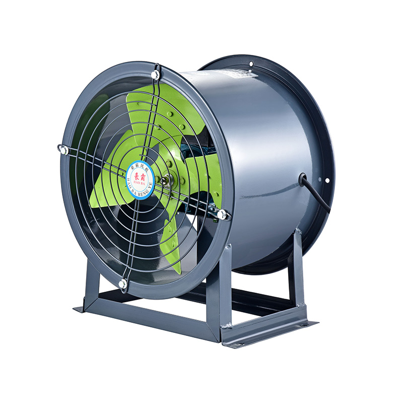
An axial flow fan moves air along the axis of rotation — the blades are angled so that as they spin, air is drawn in from one face and expelled from the other in a straight path. This is fundamentally different from centrifugal fan designs, where air is redirected radially. The implications for installation are direct: airflow must have a clear, unobstructed path along the axis, and anything that disrupts that path — a nearby wall, a poorly positioned obstruction, or a restricted inlet — reduces efficiency and increases noise.
Understanding this working principle helps clarify why so many common installation errors cause noise problems specifically. When airflow is partially blocked, the blades work harder, turbulence increases, and the acoustic performance that was engineered into the unit deteriorates. Correct installation is, in a real sense, the completion of the noise-reduction design — not an afterthought.
How Blade Angle and Rotation Direction Affect Airflow
Before installation, confirm the intended airflow direction for the unit and match it to the ventilation requirement of the space. Most axial fans are labeled with an arrow indicating rotation direction and airflow direction. Installing the unit in reverse orientation — which happens more often than equipment suppliers would prefer — results in reduced airflow volume and higher operational noise, because the blade geometry is optimized for air movement in one specific direction.
Check this before the unit is mounted. Correcting it afterward requires dismounting, reorientation, and remounting — work that could have been avoided with a two-minute check before installation began.
Site Assessment: What to Evaluate Before Mounting
Choosing the Right Position Is More Complex Than It Appears
The instinct is to place the fan where it is physically convenient — where a hole can be cut without structural difficulty, where the electrical supply is nearby, where access for future maintenance is manageable. These are valid considerations, but they should be secondary to the airflow logic of the space.
For a factory workshop, effective ventilation requires air movement that addresses the actual sources of heat, fumes, dust, or humidity in the space. A fan positioned correctly from a structural standpoint but in a location that creates dead zones in the airflow pattern will ventilate the duct or wall opening well while leaving the working area largely unaffected.
Site assessment questions worth working through before marking the mounting position:
- Where are the primary heat or contaminant sources in the space?
- What is the natural airflow path, and does the fan position work with or against it?
- Is there a clear path from the inlet to the outlet, or will the airflow need to navigate around obstructions?
- Is the mounting surface structurally adequate to support the fan weight and absorb operational vibration?
- Will the fan be accessible for cleaning and blade inspection without requiring disassembly of surrounding structures?
Getting these questions answered before drilling anything saves significant rework later.
Distance from Walls, Ceilings, and Obstructions
An axial fan requires adequate clearance on both its inlet and outlet faces. Mounting too close to a wall surface on the inlet side restricts the volume of air entering the unit, which forces the motor to work harder and increases noise generation. On the outlet side, proximity to obstructions causes backpressure that similarly degrades performance.
The manufacturer's documentation for a specific unit will specify minimum clearance distances. In the absence of that documentation — which can happen with units sourced from a wholesale axial flow fan supplier without detailed installation support — a practical rule is to ensure the inlet and outlet faces have clearance at least equal to the fan diameter.
Wall Mounted Axial Flow Fan Installation: Step-by-Step
Preparing the Mounting Surface
Wall-mounted installation is the most common configuration in factory workshops, and it carries specific structural requirements that differ from ceiling or duct-mounted setups.
Step 1 — Surface evaluation
Confirm that the wall material can support the combined weight of the fan and its bracket, plus the dynamic load from vibration during operation. Hollow partition walls, older masonry with surface deterioration, and lightweight panel systems may require reinforcement or alternative mounting strategies.
Step 2 — Bracket and anti-vibration preparation
The mounting bracket should be rated for the fan weight with an adequate safety margin. Between the bracket and the wall surface, fit anti-vibration pads or mounts — rubber or elastomeric isolators that interrupt the transmission of operational vibration into the wall structure. This is one of the most consistently overlooked steps in field installation, and it is directly responsible for a large proportion of noise complaints in otherwise well-specified installations. The fan generates low noise. A bracket transmitting vibration into a resonant wall structure generates considerably more.
Step 3 — Positioning and leveling
Mark the mounting hole positions carefully. A fan that is not level will have uneven blade tip clearances, which creates asymmetric airflow and audible noise variation across the rotation cycle. Use a level at the bracket stage, not after the fan is hung.
Step 4 — Fastener selection
Use fasteners appropriate to the wall material — chemical anchors for masonry, through-bolts where structural members allow, expansion anchors only where the wall material and loading confirm their suitability. Undersized or incorrectly specified fasteners that work loose under vibration are both a performance problem and a safety issue.
Step 5 — Fan body installation
Mount the fan body to the bracket according to the manufacturer's sequence. Tighten fasteners evenly and to specification — overtightening can distort the fan housing, and undertightening allows movement during operation.
Electrical Connection: What Cannot Be Skipped
Grounding Is Non-Negotiable in Industrial Environments
Factory workshop electrical environments carry real hazards. A fan unit that is not properly grounded creates a shock risk that is unacceptable in occupied industrial spaces. Before any electrical connection is made, confirm that the site's electrical supply includes a functional grounding path, and that the fan's grounding terminal is connected to it.
This is not a technicality — it is a basic safety requirement. Any axial flow fan factory supplying units for industrial installation will include grounding instructions in the product documentation. Following them is mandatory, not optional.
Voltage and Phase Compatibility
Confirm that the supply voltage and phase configuration match the fan's electrical specification before connection. Connecting a three-phase fan to a single-phase supply, or operating a unit outside its rated voltage range, causes motor overheating, accelerated bearing wear, and reduced service life — none of which will be apparent immediately, but all of which will shorten the useful life of the equipment.
For units sourced as China axial flow fan products through international distribution, voltage compatibility is particularly important to verify, since supply standards differ between markets. The product documentation should specify the rated voltage and acceptable range. If documentation is absent or unclear, request it from the supplier before energizing the unit.
Wiring and Connection Points
- Use cable suitable for the electrical load and environmental conditions of the installation — moisture, heat, and mechanical abrasion are all relevant in factory contexts
- Secure cables to prevent movement and chafing against edges or moving components
- Ensure all terminal connections are tight — loose connections cause arcing, heat buildup, and eventual failure
- Where the installation includes a speed controller or variable frequency drive, confirm compatibility with the fan motor type before connection
Airflow Direction and Ventilation Path Optimization
Does the Airflow Direction Match the Ventilation Goal?
This question is worth asking explicitly because incorrect airflow direction is one of the more common installation errors and one of the least obvious after the fact. An axial fan moving air in the wrong direction — exhausting where it should be supplying, or supplying where it should be exhausting — can reduce air quality in a workshop by creating recirculation rather than fresh air exchange.
For most factory workshop applications, the fan is configured to exhaust contaminated or heated air to the exterior while replacement air enters through a separate inlet — natural openings, louvered vents, or a dedicated supply fan. The exhaust fan should be positioned to draw air from the zone where heat or contaminants are generated, not from a clean area that creates a shortcut path bypassing the working zone entirely.
Avoiding Recirculation
Recirculation occurs when exhaust air re-enters the building through nearby openings and is immediately drawn back through the fan system. It is most common when the exhaust outlet and the fresh air inlet are positioned too close together on the exterior of the building.
On the interior side, furniture layout, machinery placement, and partition walls can all redirect airflow in ways that were not anticipated during the installation design phase. Walking the space after commissioning — noting where air movement is felt and where it is not — provides practical information about whether the ventilation design is working as intended.
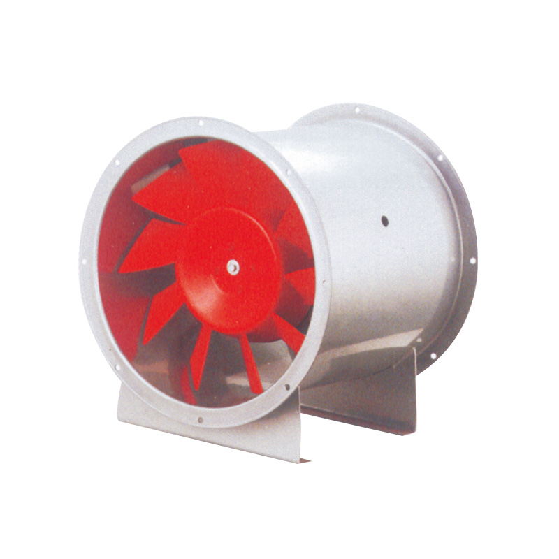
Bifurcated Axial Flow Fan Installation Considerations
Why High-Temperature and Hazardous Environments Require a Different Approach
A bifurcated axial flow fan is designed specifically for applications where the airstream itself contains heat, fumes, or potentially flammable or corrosive content. In standard axial fan designs, the motor sits directly in the airstream. In a bifurcated design, the motor is located outside the airstream — in a separated housing — so that the motor is not exposed to the conditions of the air being moved.
This structural difference has installation implications. The motor housing requires its own ventilation to prevent heat buildup, and the airstream path through the fan body must be sealed from the motor compartment to maintain separation. Installation of bifurcated units in chemical processing areas, paint spray booths, or high-temperature exhaust applications should follow the manufacturer's application-specific guidance rather than standard installation procedures.
Confirming the Right Unit for the Application
Before installing a bifurcated unit, confirm that it has been specified for the actual conditions of the application — the temperature range, the contaminant type, and the required protection rating. Using a standard fan in an environment that warrants a bifurcated design is not just a performance issue — it creates a genuine safety risk in environments where motor exposure to the airstream could cause ignition or accelerated degradation.
Comparing Installation Requirements Across Fan Types
Installation FactorStandard Wall Mounted FanBifurcated Axial FanCeiling or Duct Mounted Fan
| Installation Factor |
Standard Wall Mounted Fan |
Bifurcated Axial Fan |
Ceiling or Duct Mounted Fan |
| Mounting surface requirements |
Solid wall, adequate load rating |
Rigid support structure, vibration isolation |
Ceiling or duct frame, load confirmation |
| Anti-vibration measures |
Bracket isolators recommended |
Critical — motor housing also needs isolation |
Flexible duct connections reduce transmission |
| Airflow direction confirmation |
Essential before mounting |
Essential — also confirm motor compartment ventilation |
Confirm duct orientation before installation |
| Electrical grounding |
Mandatory |
Mandatory — heightened importance in hazardous areas |
Mandatory |
| Clearance requirements |
Inlet and outlet faces |
Inlet, outlet, and motor compartment |
Inlet face and duct connection |
| Maintenance access |
Front face accessible |
Motor compartment separate access required |
Depends on ceiling or duct configuration |
Post-Installation Checks Before Full Operation
What to Verify Before Running the Fan at Full Load
A short commissioning sequence before the unit goes into continuous operation catches problems that are far easier to address at this stage than after weeks of running.
Checks to carry out:
- Visual inspection: confirm that no tools, fasteners, or debris are present in the fan housing or near the blades
- Blade clearance: manually rotate the blades (with power off) to confirm they move freely without contact with the housing
- Fastener tightness: check all mounting fasteners, bracket bolts, and electrical terminals
- Short test run: energize the unit briefly and observe for unusual noise, vibration, or smell. A brief burning smell at initial startup can indicate contamination on a new motor — this typically clears quickly. Persistent smell, visible smoke, or unusual electrical odor requires immediate shutdown and investigation.
- Airflow confirmation: stand at the intended inlet and outlet positions to confirm air is moving in the expected direction and volume
- Vibration check: with the unit running at operating speed, place a hand on the mounting bracket and wall to assess vibration transmission. Excessive vibration felt at the wall surface indicates that anti-vibration measures are insufficient or that a fastener has worked loose.
Noise Level Assessment After Commissioning
A properly installed low noise axial flow fan should operate at a noise level consistent with the unit's specification. If the installed unit is noticeably louder than expected, the likely causes are:
- Blade contact with housing due to misalignment or distorted housing
- Anti-vibration isolators absent or incorrectly installed
- Airflow obstruction creating turbulence and aerodynamic noise
- Loose components — panels, covers, or fasteners — that rattle at operating frequency
- Incorrect blade rotation direction
Each of these is addressable. The key is identifying which applies before concluding that the unit itself is defective.
Maintenance Practices That Preserve Long-Term Performance
Blade and Housing Cleaning
Dust and particulate accumulation on fan blades is a common cause of gradual performance decline and increasing noise in factory environments. Uneven dust buildup on blades creates imbalance, which introduces vibration that the original installation successfully controlled.
A periodic cleaning schedule — monthly in high-dust environments, quarterly in cleaner ones — maintains both airflow performance and acoustic quality. Cleaning should always be done with power isolated and locked out.
Bearing and Fastener Inspection
Fan bearings are wear components. Their service life depends on operating conditions, load, and maintenance frequency. Periodic bearing inspection — listening for changes in running noise that indicate wear, checking for increased vibration — allows replacement before bearing failure causes secondary damage to the motor or housing.
Fastener checks should be part of the same maintenance visit. Vibration gradually loosens fasteners even in well-installed units, and a mounting bracket that has shifted by a few millimeters creates problems that were not present at commissioning.
Correct installation of a Low Noise Axial Flow Fan is not complicated, but it is detailed — and the details that are skipped at the installation stage have a way of reappearing as performance problems, noise complaints, and maintenance costs over the operating life of the unit. The mounting position, the anti-vibration measures, the electrical connections, the airflow direction confirmation, and the commissioning checks described above are all established practice, not theoretical ideals. Installations that follow them consistently deliver the performance the equipment was designed to provide. Those that take shortcuts produce results that erode confidence in the product itself, when the real issue is how it was put in. For procurement teams sourcing axial fans for factory or industrial applications — whether evaluating wholesale axial flow fan options or working directly with an axial flow fan factory on project-specific requirements — the quality of installation guidance and technical support provided alongside the equipment is worth weighing alongside the product specification itself. Taizhou Haoba Electromechanical Co., Ltd. manufactures a range of axial flow fan products including wall mounted axial flow fan and bifurcated axial flow fan configurations, with technical documentation and support resources designed to assist buyers and installation teams in achieving correct setup and sustained performance across industrial ventilation applications.
 English
 русский
 عربى
عربى